Mon 09 February 2004 |
| First job early today was to clean up and re-scuff the mess from yesterday. Obviously we don't want lots of layers of paint (too much added weight and looks bad) so I took my time over this and we only used acetone rather than the etch acid as preparation. | 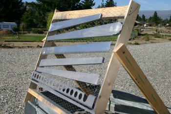
|
| The aileron mounts all sorted. By the end we had the bucking system under control and feel a little more comfortable with it, more practice needed. | 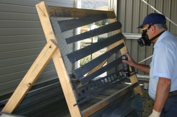
|
| We then baked them in Central Otago sun mark "max". Seemed to all workout OK. | 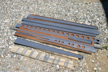
|
| The left wing was also on today's list, so I started riveting the aileron attach brackets on. The side and top 3 aft rivets can all be done with the pneumatic squeezer the rest needs to be shot / bucked. | 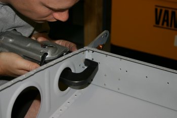
|
| What NOT to do. The pressure used for the squeezer is around 90 PSI, the pressure needed for the 3X rivet gun for AD4 rivets is around 40 PSI. Guess what this is a picture of??? The rivet gun now has large black letters of "PRESSURE" written on it....... We carried on and came back to the bad ones that needed to be drilled out. | 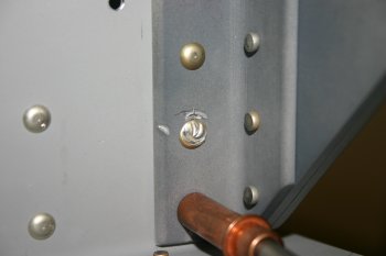
|
| The remnants of the bad rivet. You can see it wasn't just the manufacture head (left side) that was a mess, the shop (right side) is also VERY wrong.... | 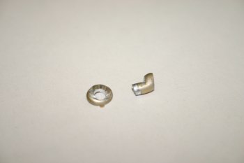
|
| The aileron brackets all mounted, the inboard bracket need the majority of rivets bucked and by the end we were feeling a little more comfortable with the whole process. More practice needed. | 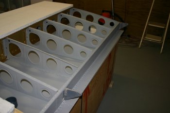
|
| The inboard mount spacing was setup the same as the right wing but I found the spacer needed to be reduced from 17/32" to a simple 1/2". After that it was all fine and dandy. | 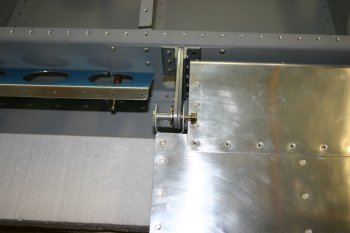
|
| This is how we 'locked' the aileron in position the meter ruler was cleco clamped to the alignment tooling holes and the magic gaffer tape was run under the top surface of the aileron and over and round the straight edge. | 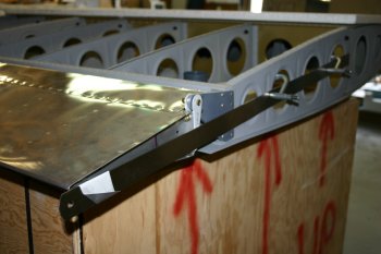
|
| Dad then started on the flap mounting on the left wing. | 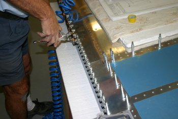
|
| The finished cleco'd piano hinge. The flap / aileron distance is again about 9/32" but the trailing edge is quite as good as the right wing although it is well within limits (about 1/32"). | 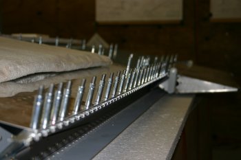
|
| We opted to the central location for the hinge wire and this required three 'tabs' to be removed. We found flush cutters worked well on the soft hinge AL. | 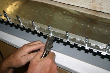
|
| I continued throughout the day working on the elevators. Including finishing the match drilling and separating the parts ready for deburring. | 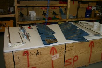
|
| The elevator counter weights are held by two bolts / screw so I drilled the #12 in the lead. This was a slow process but use BoeLube and it all works OK. | 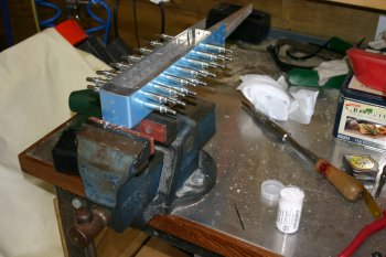
|
| Then it is the normal, take apart, debur and prep all the parts. | 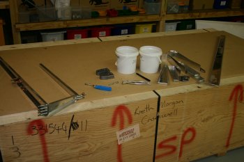
|
| Then dimple all the skin rivet locations, this ended up using most of the dimpling tools available. That was all for today, hopefully another batch of priming first thing tomorrow. | 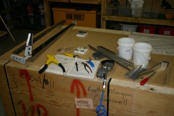
|


